

- Watch out
- What it costs
- Experienced readers
- Remember
- In BIMpedia
No single view shows a structure completely. A plan hides heights; an elevation hides depth; a section shows only where it is cut. A drawing set is a set of views that, together, describe one thing, and reading it means moving between them.
| View | You are looking | Shows best |
|---|---|---|
| Plan | Down from above | Layout, lengths, positions |
| Elevation | From the side | Heights, levels, profiles |
| Section | At a cut through it | Thicknesses, layers, how parts fit |
| Detail | At a small part, enlarged | Connections, reinforcement, fixings |
Moving between views
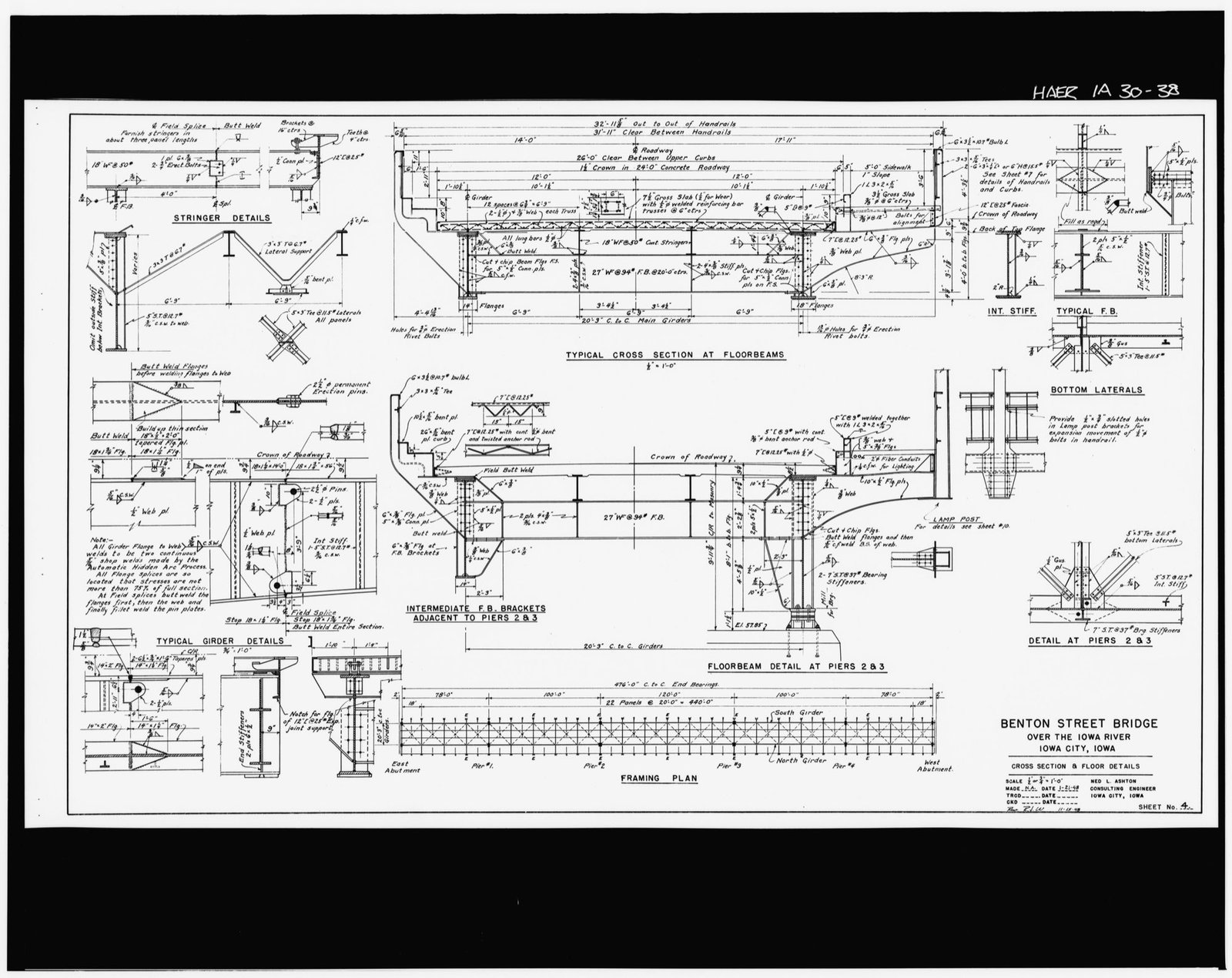
Sheet 4, cross section and floor details: a typical cross section at the floorbeams, details of girders and stringers, the exceptions at piers 2 and 3, and the framing plan along the bottom.
Benton Street Bridge, Iowa City (Ned L. Ashton, consulting engineer, 1947–48). Historic American Engineering Record, HAER IOWA,52-IOWCI,4-. Library of Congress, Prints and Photographs Division. Public domain. Source
On sheet 4 you can follow how the views relate:
- The typical cross section gives the deck: 26'-0" clear between the upper curbs, a 24'-0" concrete roadway with a 1½" crown, a 5'-0" sidewalk, and main girders 20'-3" centre to centre.
- The framing plan along the bottom shows the same girders from above, with 22 panels of 20'-0" between end panels of 18'.
- Details at piers 2 and 3 show where the typical arrangement doesn't apply.
- A callout sends you to sheet 10 for the lamp post brackets.
Check the views against each other
The fastest check of any set is arithmetic. Add up a chain of dimensions and compare it with the overall figure; find the same dimension on two sheets and compare them. On this set, sheet 4's framing plan (18' + 22 × 20' + 18' = 476') agrees with sheet 1 (476' between end bearings). When a check like this fails, one of the sheets has been edited, or is from another revision.
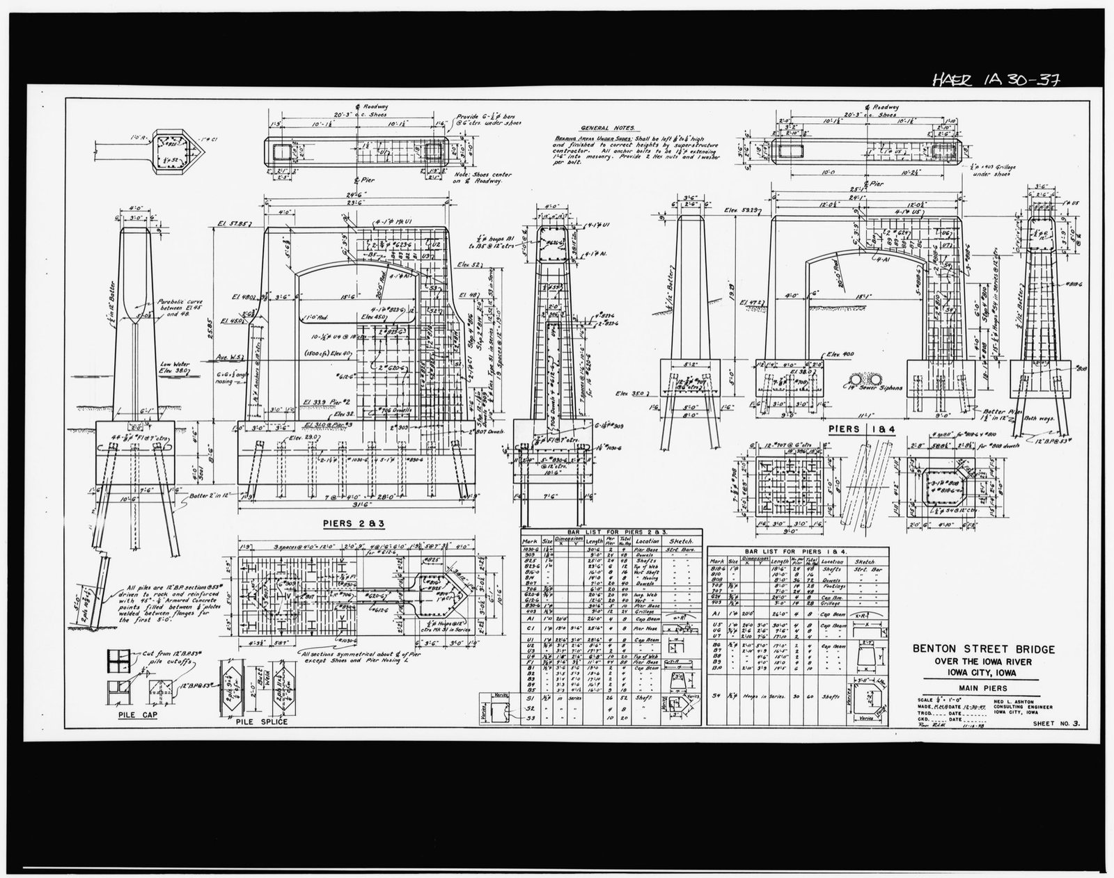
Sheet 3, the main piers. Open it full size and find the levels that tie each pier back to the general elevation on sheet 1.
Benton Street Bridge, Iowa City (Ned L. Ashton, consulting engineer, 1947–48). Historic American Engineering Record, HAER IOWA,52-IOWCI,4-. Library of Congress, Prints and Photographs Division. Public domain. Source
The architectural section shows a 3.0 m floor-to-ceiling height in the corridor. The services drawings, drawn from an earlier plan, assume a 600 mm ceiling void. Nobody compares the two, and on site the ducts don't fit above the corridor ceiling.
The coordinator cuts the same section through the federated model, lays it next to the architectural section and the services drawing, and checks three numbers: slab level, ceiling level and duct depth. The 150 mm shortfall is found in a meeting, not on site.
Open sheet 4 of the Benton Street Bridge above, full size.
- What is the clear width between the upper curbs, and the width of the concrete roadway?
- The slab is noted as "7½" gross slab (½" for wear)". What thickness carries the load, in inches and in millimetres?
- How far apart are the main girders, centre to centre, in metres?
Key takeaways
- Plan, elevation and section are three directions of looking at the same thing; details are close-ups at a larger scale.
- Section marks and detail callouts tell you where a view is cut and which sheet it is drawn on.
- 'Typical' views apply wherever nothing else is shown; exceptions are drawn separately.
- Add up chains of dimensions and compare views: it is the fastest drawing check there is.